Customers often ask me about the best way to implement a centralised egress inspection architecture for workloads across multiple regions. Since the launch of GCP Network Connectivity Center, organisations are moving away from the traditional VPC peering model to adopt the flexible and scalable NCC Hub and Spoke architecture.
Network Connectivity Center is an orchestration framework that enables network connectivity among VPCs that are connected to a central management resource called NCC Hub. This design uses two types of spokes:
VPC Spokes provide inter-VPC network connectivity at scale, reducing the operational complexity of managing individual pair-wise VPC Network Peering connections through centralised NCC Hub.
Hybrid Spokes provide VPC networks connectivity to on-premises or other cloud provider networks. These external networks can be reachable through any type of hybrid spoke. Hybrid spokes consist of:
- HA VPN Tunnel
- Cloud Interconnect VLAN attachments
- Router Appliance
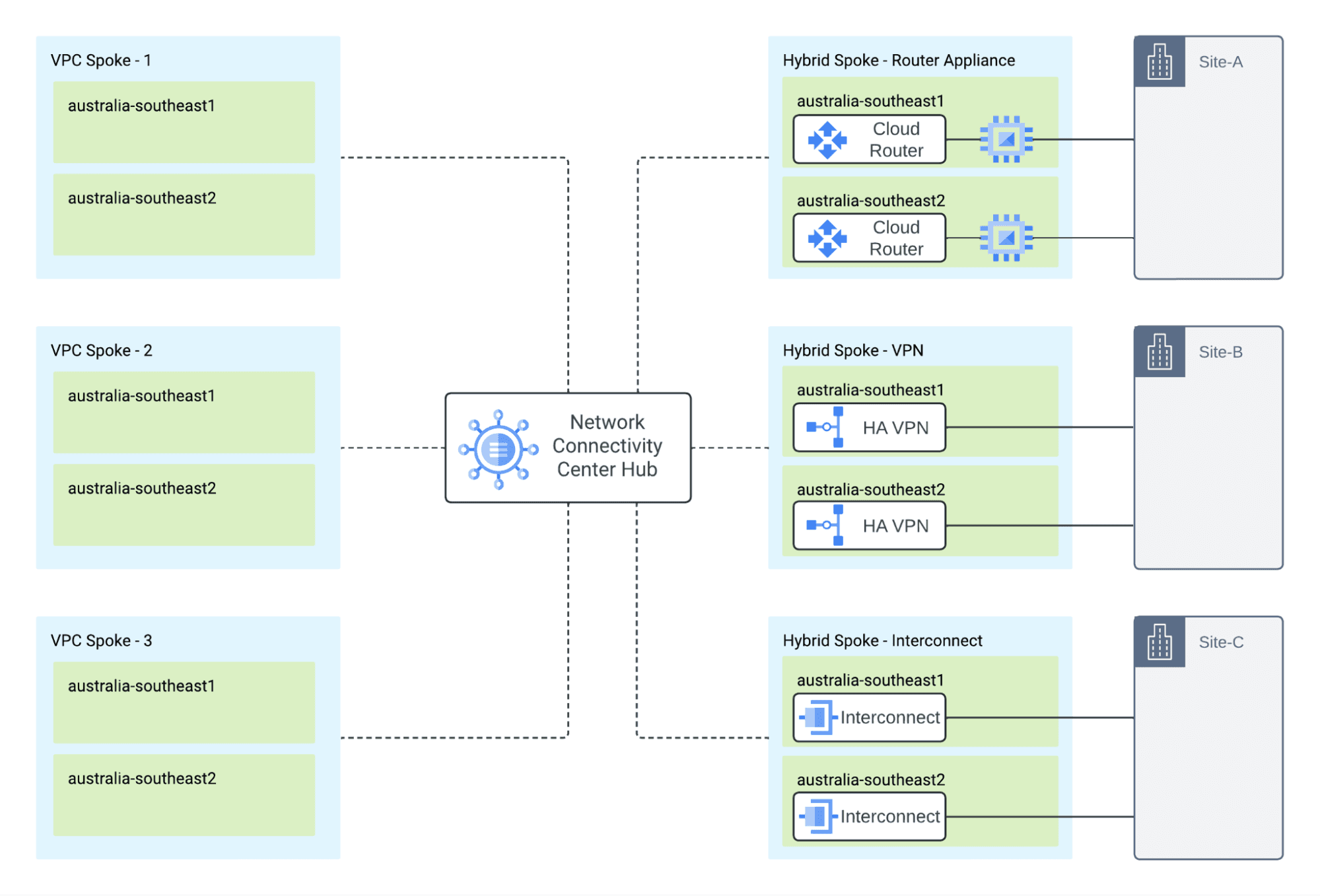
Route exchange with spokes enables scalable any-to-any connectivity between VPC Spokes and hybrid spokes, however it comes with limitations where IPv4 static default routes exchange across VPC spokes and default routes pointing to internal passthrough Network Load Balancer virtual IP address in other VPC spokes are not supported, therefore workloads in a VPC Spoke cannot reach the internet through the centralised Network Virtual Appliances that are deployed in a traditional way behind a load balancer with a static default route exported.
This is where NCC Router Appliances come into play, offering a solution to these challenges by enabling more flexible and robust routing configurations, ensuring that all workloads can maintain necessary connectivity through centralised appliances.
Update: NCC now lets a static route in one VPC spoke use an internal passthrough Network Load Balancer in another VPC spoke as its next hop, so the load balancer pattern also works across VPC spokes. Router appliances remain the better fit when you want BGP to handle regional preference and failover.
Network Virtual Appliances with NCC Router Appliances
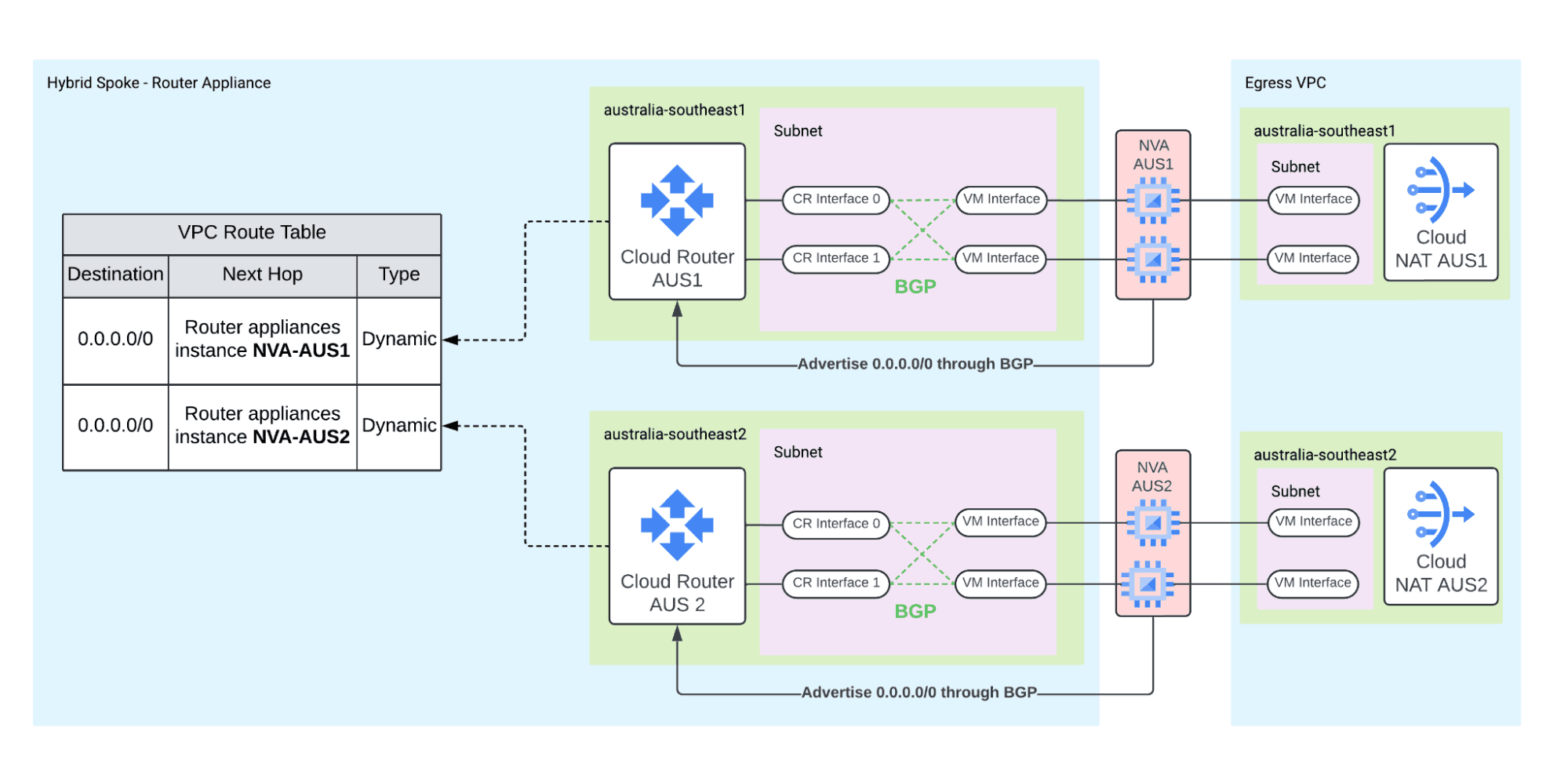
NCC Router Appliances are a type of hybrid spoke that allows the creation of BGP sessions between GCP Cloud Router and any Network Virtual Appliances that support BGP, including solutions like Palo Alto Networks VM-Series and Fortinet FortiGate firewalls. Router appliance spokes are regional, so this design uses one spoke per region. Each NVA needs IP forwarding enabled, a static internal IP address, and firewall rules that allow BGP (TCP port 179) from the Cloud Router interfaces.
Once the Network Virtual Appliances are installed, interfaces on the GCP Cloud Router are configured to establish Border Gateway Protocol (BGP) peering with the appliances. To ensure redundancy, two interfaces must be created on each Cloud Router, with both interfaces associated with the same subnet as the corresponding appliance's interface. Each NVA peers with both interfaces, so a region with two NVAs runs four BGP sessions. BGP then facilitates the dynamic exchange of routes between the Cloud Router and the NVAs.
Network Virtual Appliances advertise the 0.0.0.0/0 prefix through BGP to the GCP Cloud Router, which then installs this prefix as a dynamic route in the VPC routing table. The route is configured with a Next Hop value pointing to the specific Router Appliance instance, identified as Router appliance instance <NVA-Name>, ensuring that all traffic going to the external networks is directed through the NVA.
In the other direction, each Cloud Router advertises a summary route for the internal ranges (10.0.0.0/8 in this setup) to the NVAs, so they send replies for the workload subnets back through the Router Appliance VPC.
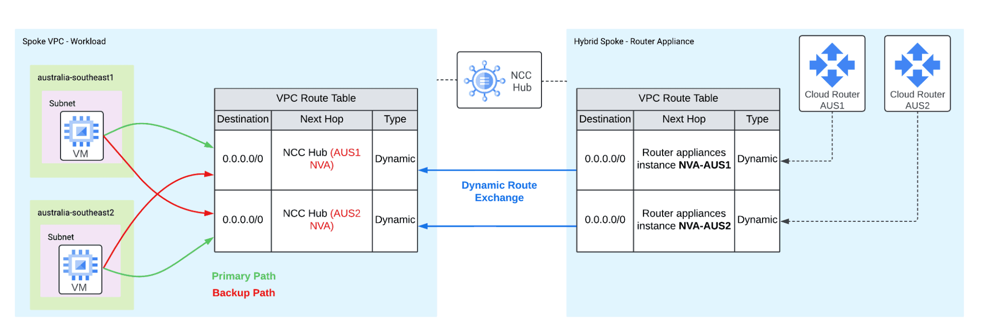
Network Connectivity Center spokes support the exchange of subnet private IPv4 address ranges and dynamic routes learned by the Router Appliance Spoke VPC through BGP, as in our case. These dynamic routes are then propagated to all workload Spoke VPCs, enabling, for example, a VM in the workload VPC to utilise these routes to reach the internet through the centralised Network Virtual Appliances.
The exported dynamic routes in the workload VPC allow resources to automatically use routes with different next hops without the need for network tags. With global dynamic routing enabled in the Router Appliance VPC, these routes are installed in every region. The NVAs in both regions advertise the default route with identical BGP attributes, and Cloud Router adds an inter-region cost to the MED of routes whose next hop is in another region. Traffic therefore prefers next hops within its own region, and only uses the next hops in other regions if the NVAs in its own region fail.
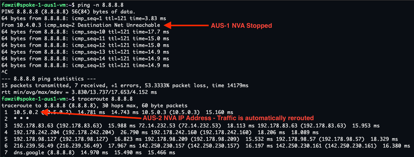
Failover occurs automatically, as routes pointing to the primary next hop are withdrawn if a failure happens. For example, if the NVAs in the AUS1 region fail, the routes they advertised, including the default 0.0.0.0/0 route, will be removed, and traffic will automatically reroute through the NVAs in the other region. Consequently, VMs in the AUS1 region will use the default route via the AUS2 NVAs.
How quickly this happens depends on how the BGP sessions go down. If an NVA shuts down cleanly, it closes its BGP sessions and its routes are withdrawn within seconds, as in the test below. If it fails without closing them, Cloud Router waits for the BGP hold timer (60 seconds in this setup) before it withdraws the routes. BFD isn't available for router appliance BGP sessions, so the hold timer is the upper limit.
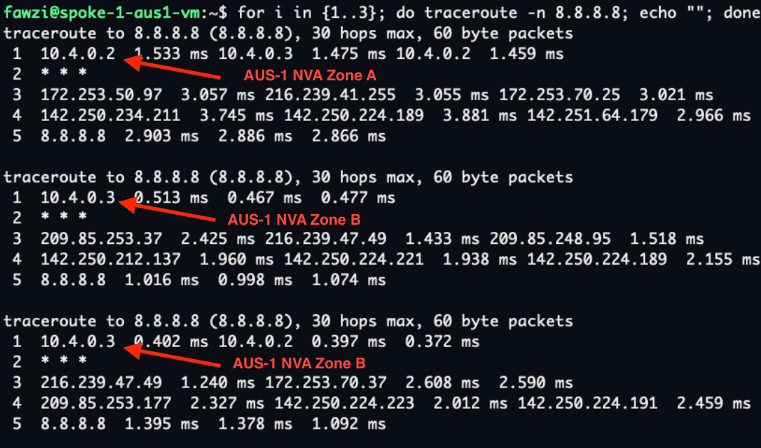
Moreover, there’s no longer a need for internal passthrough Network Load Balancers, as the next hop for the BGP routes is pointed directly to the NVAs. GCP will automatically perform equal-cost multipath (ECMP) routing to spread traffic across multiple NVAs within the same region. Google Cloud hashes each packet on its five-tuple, or its three-tuple when the packet has no ports, so packets of one connection usually use the same NVA. Google doesn't guarantee this, so a connection can occasionally move to the other NVA. For ECMP to apply, the NVAs in a region must advertise the default route with an identical AS path, origin and MED.
Design considerations
The workload VPCs must not have the default route to the internet gateway. Google Cloud prefers a VPC's own static and dynamic routes over the dynamic routes that NCC brings in from hybrid spokes, and the system-generated default route counts as a local static route. While that route exists, the 0.0.0.0/0 routes from the NVAs are never used. In this setup, the workload VPCs are created without it. They keep the routes to private.googleapis.com and restricted.googleapis.com through the default internet gateway, so Google API traffic doesn't go through the NVAs.
The Router Appliance VPC is also created without a default route. NCC requires the routing VPC of a hybrid spoke to have no local static routes that overlap the dynamic routes the spoke exports, and every IPv4 range overlaps 0.0.0.0/0. An overlapping static route can make VPC spokes lose connectivity.
Cloud NAT doesn't translate forwarded traffic by default. Its default rule only covers a VM's primary internal IP address and alias IP ranges, not the workload addresses that the NVAs forward. In this setup, each NVA masquerades (source NATs) outbound traffic to its egress interface address. Cloud NAT then translates it, and the replies come back to the same NVA.
Cloud Router withdraws an NVA's routes only when its BGP sessions go down. An NVA that keeps BGP up but stops forwarding traffic still attracts traffic, so monitor the forwarding path as well as the BGP sessions.
End-to-end testing
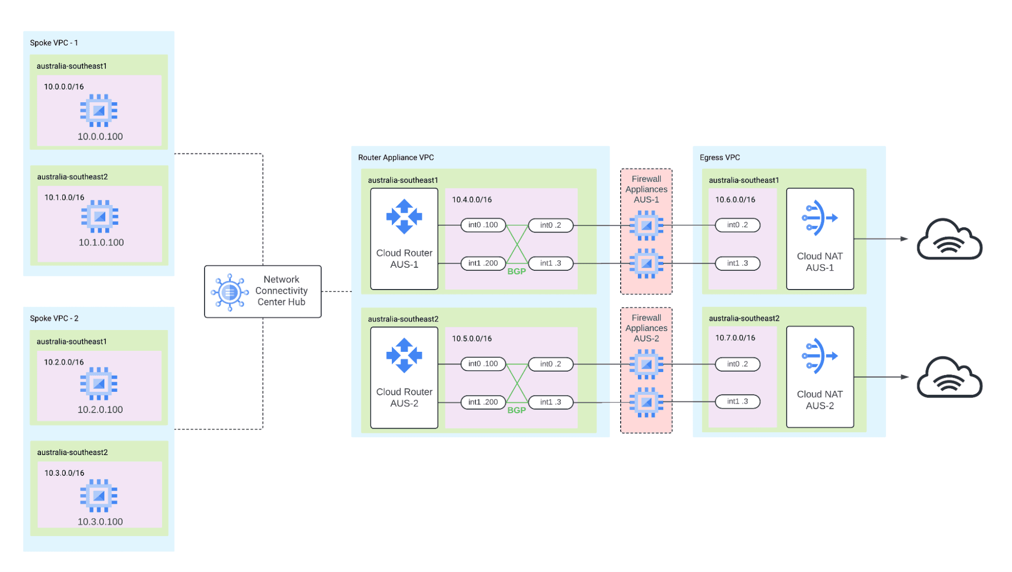
For end-to-end testing, the focus is on egress traffic from a VM located in Spoke VPC-1 in the australia-southeast1 region, as shown in the diagram below.
To route the egress traffic from this VM to the internet, two pairs of Network Virtual Appliances (NVAs) are deployed in australia-southeast1 and australia-southeast2, with the following IP addresses:
AUS-1 NVAs: 10.4.0.2 and 10.4.0.3
AUS-2 NVAs: 10.5.0.2 and 10.5.0.3
For testing, the NVAs are e2-micro VMs running FRRouting for BGP and iptables for forwarding and masquerading, not commercial firewalls.
This setup not only allows for an evaluation of how the VM routes its traffic through the appropriate NVAs to access the internet, but it also enables testing of how GCP’s equal-cost multipath (ECMP) routing spreads traffic across multiple NVAs within the same region.
Conclusion
The NCC Hub and Spoke architecture with NCC Router Appliances gives workloads in every region a path to the internet through centralised NVAs. BGP handles failover between regions, ECMP spreads traffic across the NVAs within a region, and there are no internal load balancers or tagged static routes to maintain.
Want to test it yourself?
The Terraform code for this setup is public at fawzihmouda/gcp-ncc-nva. It deploys the NCC hub, the spoke VPCs, the router appliance spokes, the NVAs, Cloud NAT and the test VMs in australia-southeast1 and australia-southeast2. It also adds an HA VPN hybrid spoke to a simulated on-premises network.
You need Terraform 1.7.4 or later and a Google Cloud project with the Compute Engine and Network Connectivity APIs enabled. Then clone the repository and apply it:
git clone https://github.com/fawzihmouda/gcp-ncc-nva.git
cd gcp-ncc-nva
terraform init
terraform apply -var project_id=YOUR_PROJECT_ID
Once it's up, connect to the test VM in Spoke VPC-1 and trace a route to the internet. The first hop alternates between the AUS-1 NVAs:
gcloud compute ssh spoke-1-aus1-vm --zone australia-southeast1-a --tunnel-through-iap
sudo apt install -y traceroute
traceroute -n 8.8.8.8
To test failover, stop both AUS-1 NVAs from another terminal and run the traceroute again. The first hop moves to the AUS-2 NVAs:
gcloud compute instances stop nva-aus1-a --zone australia-southeast1-a
gcloud compute instances stop nva-aus1-b --zone australia-southeast1-b
The setup creates billable resources, so remove them when you're done:
terraform destroy -var project_id=YOUR_PROJECT_ID